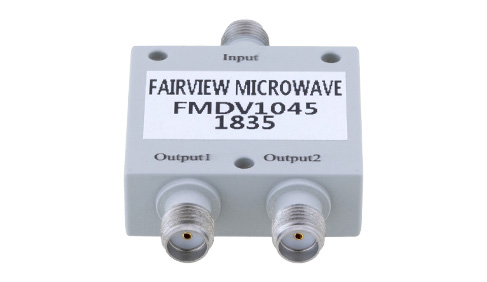
Introduction to RF Power Dividers

It is often the case with RF systems where it is necessary to divide or combine the electromagnetic (EM) energy from two or more RF paths. It may be that a high power signal is needed or a high power signal generator is used and split to several paths, either way, RF Power Dividers/Combiners are the necessary component for this function. Power dividers/combiners are typically passive RF structures that are designed in such a way that an incoming signal is evenly split down an even number of paths. It is possible to design and fabricate odd number power divider/combiners, however, this is less common than even port numbered power dividers/combiners. The most widely available power combiner/dividers are 2-way, 4-way, and 8-way. As the tolerances and complexities of power divider/combiner design scale with the port count, it is rare to find power divider/combiners beyond 16-way. It is theoretically possible to have any number of power dividing/combining ports, there is just a practical utility for a given port count for most RF systems.
Even numbers power divider/combiners are most often designed to evenly divide or combine the inputs/outputs. An RF directional coupler is the nomenclature generally used when the coupling ratio for the ports is not even and the coupling factor is a small portion of the incoming/outgoing signal energy. An RF hybrid coupler is a nomenclature given to a special class of directional coupler that evenly splits the signal energy from one port to two other ports with either a 90 degree or 180 degree phase difference. This differs from typical RF power dividers/combiners where the phase is designed to match among every output port, which means that each signal path from the single-port to multiple ports is equal in electrical length (phase length).
For every additional set of ports, a reactive power divider will result in each output port with half the available power, or double if the divider is used in a combiner configuration. For instance, a 2-way RF Power Divider with a reactive design has a 3-dB signal power reduction from the input signal port to output signal ports. An 8-way RF Power Divider with a reactive design will have a 9 dB loss/gain due to the 1:8 ratio. There are also resistive power dividers where the loss per signal path is double that of reactive power dividers. Resistive power dividers are generally made using lumped elements and can be very compact and broadband, but have limited power handling, high loss, and poor isolation compared to reactive power dividers. Reactive dividers/combiners are made using transmission or waveguide structures that exhibit generally better RF performance, but are typically limited in frequency range and larger in size than resistive power dividers/combiners.

