

The diversity of RF and wireless applications has driven the diversity of RF coaxial connectors. For essentially all RF applications, there is an RF coaxial connector. It is impossible to cover everything about RF coaxial connectors in a single blog, let alone a book. The goal with this blog is to merely provide a high-level understanding of the various parameters and general types/applications for RF coaxial connectors.
Type-N Coaxial Connector
Related articles
Peter McNeil | Feb 13, 2025 | RF Interconnects
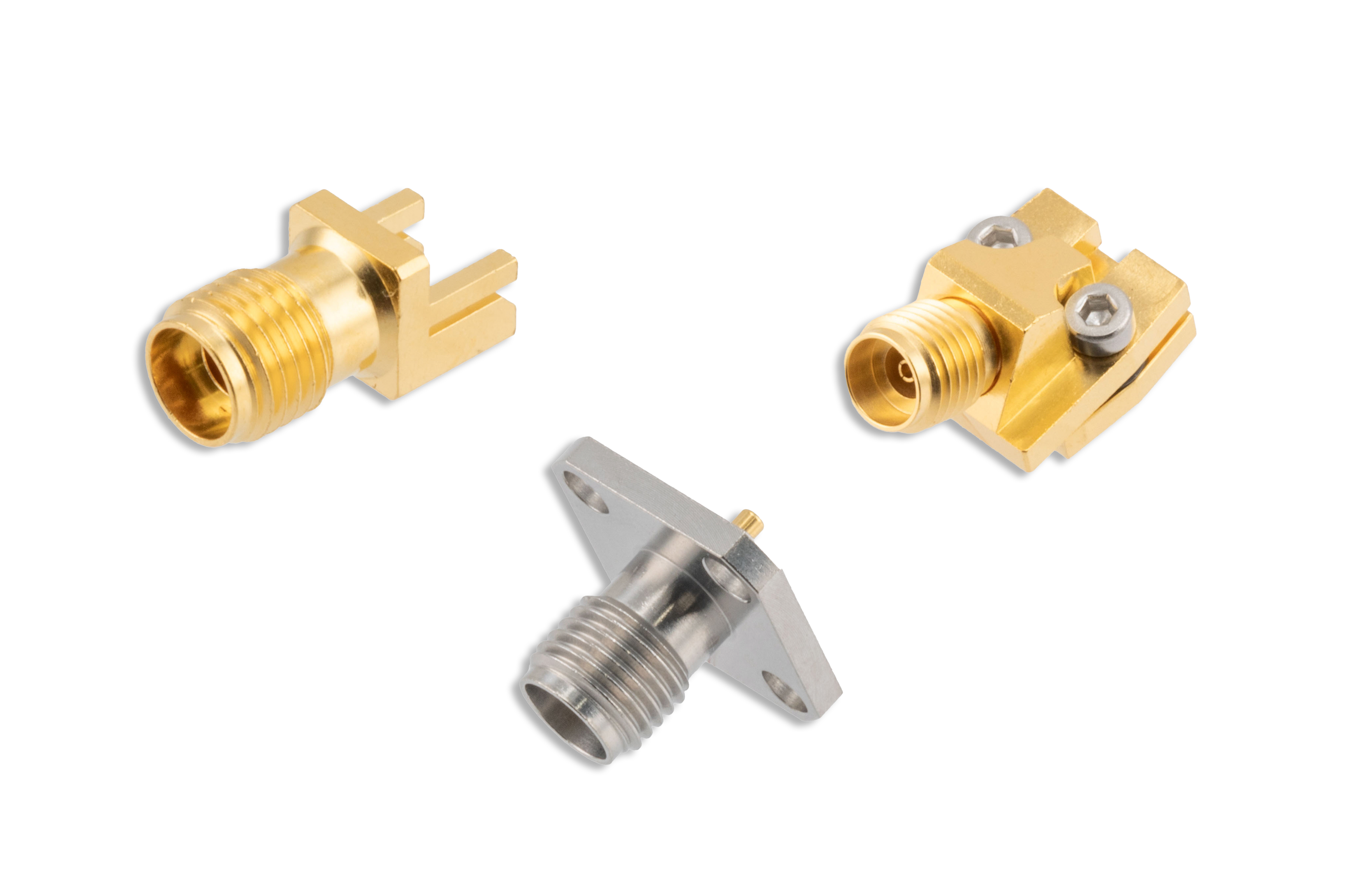
Designing high-performance RF systems often requires overcoming space limitations and optimizing signal routing with specialized components, such as angled PCB connectors. Unlike traditional straight connectors, PCB connectors allow for a more flexible orientation, making them ideal for compact designs where efficient use of space is crucial.
For example, when prototyping or working with tight spaces, the 1.85mm, female PCB mount vertical launch connector offers a clamp attachment design for easier installation. This product in particular supports up to 67 GHz performance, making it a reliable option for applications requiring high-frequency signal transmission.
Angled connectors like this one not only optimize space but also ensure that your system maintains low signal loss and high-frequency integrity, even when space is at a premium. Whether you're working on satellite communications, aerospace systems, or military radar systems, choosing the right connector can significantly enhance system performance.
Similarly, for applications requiring high-frequency performance and easy integration, products like the 2.4mm Jack PCB Mount End Launch and the 2.4mm Jack Solderless PCB Mount offer solutions that streamline installation and improve overall system reliability. With 50 GHz performance and minimal signal loss, these connectors are designed to meet the rigorous demands of high-performance systems.
How to Choose the Right Printed Circuit Board Connectors for Your Application
Selecting the appropriate RF PCB connectors for your system requires careful consideration of several factors, including the frequency range, VSWR (Voltage Standing Wave Ratio), mounting options, and the available space in your design. Each of these factors plays a crucial role in ensuring the efficiency and performance of your RF system.
· Frequency Range: The frequency range is one of the most important factors when choosing a connector. RF connectors that support up to 50 GHz, are ideal for applications that demand high-frequency performance. It's essential to select connectors that match the frequency requirements of your system to avoid signal degradation and ensure the integrity of your data transmission.
· VSWR: VSWR is an important indicator of signal integrity. A low VSWR ensures minimal signal loss, meaning your system can transmit signals with high efficiency. When evaluating connectors, always check the VSWR specifications to ensure they meet the requirements of your application.
· Mounting Options: The mounting method of your connector can have a significant impact on the ease of installation and the overall design of your system. End-launch connectors are excellent for systems where space constraints require a compact and efficient connector without sacrificing performance.
· Available Space: The physical space available in your design is another critical factor to consider. For systems with tight space requirements, narrow-body connectors high performance while occupying minimal space. These types of connectors are ideal for applications in military defense or satellite communications, where every inch of space matters.
Optimizing System Performance with the Right Connectors
Choosing the right connector can dramatically impact the performance of your RF system. For industries such as military defense, satellite communications, and RF testing, where precision is critical, high-performance connectors are a must.
These connectors also provide flexibility in routing and space-saving benefits that are essential in modern RF designs. Whether you need angled connectors for tight spaces or end-launch connectors for ease of integration, the right product ensures your system will operate at its best.
Future-Proof Your RF Designs with Top-Quality Printed Circuit Board Connectors
When designing your next high-performance RF system, consider the impact that these connectors and end launch connectors can have on your system’s performance. The connectors discussed here offer high-frequency performance, low-loss transmission, and the versatility required for demanding applications. Whether you’re working in telecommunications, military defense, or test & measurement, choosing the right connector ensures your system operates efficiently, even in tight spaces.
Our PCB connectors provide optimal signal integrity, reduced installation time, and ensure your systems perform at their best. Explore our range of high-performance RF PCB connectors today and get the reliability you need for your next big project.
Peter McNeil | Jan 04, 2024 | RF Interconnects
RF Interconnect is another term for RF connections between devices, boards, ports, RF cable assemblies, waveguide, probes, antenna, and etc. As discussed in a previous blog post, What is an RF Connection, RF interconnects are a method of transferring RF signals from one node to another either conductively, through a transmission line (RF coaxial connectors/ coaxial cable assemblies), or through a waveguide. It can be argued that an RF antenna is also a form of interconnect, though it is really a transducer that converts electrical signals carried conductively to a free-space wavefront.
When speaking of RF interconnect, this generally refers to connections between circuit boards, devices, subsystems, systems, and between interconnects. The reason RF interconnects are used, especially transmission lines and waveguides, is because containing the RF signal energy in a transmission line or waveguide is generally a much more efficient method of transferring that signal energy from one point to another, that signal is shielded to some degree from interference/noise injections from outside sources, and these types of connections help to ensure that the signal is harder to intercept, jam, block, or otherwise interfere with.
There are a variety of types of transmission lines and waveguides, as well as other types of RF interconnects. The most common types of RF transmission lines that most engineers and professionals are aware of are coaxial transmission lines. These make up the bulk of RF interconnects between modules, subsystems, and systems. Waveguides such as rectangular, circulatory, and elliptical waveguides are also commonly used for high power, precision, and extremely high frequency signals in the millimeter-wave range. There are other types of transmission lines, including planar transmission lines used on planar substrates/laminates, such as PCB, low-temperature co-fired ceramic (LTCC), high-temperature co-fired ceramic (HTCC), flex-PCBs, semiconductors, and others. Example planar transmission lines are coplanar transmission lines and striplines, of which there are a variety of configurations. There are also planar waveguides, such as a microstrip.
There are also a variety of different connector and adapter styles that should be included in the RF interconnect categories. These include adapters from different transmission line types, such as a planar transmission line to a coaxial transmission line, or between different types of coaxial connector types. There are also adapters between coaxial transmission lines and waveguides. It is important to note here that coaxial transmission lines are broadband RF signal carrying medium, while waveguides are banded based on the geometry and structure. Hence, any adapter between a coaxial transmission line and a waveguide will have a lower cutoff frequency limited by the waveguide and a higher cutoff frequency either limited by the coaxial transmission line or waveguide, whichever is lower.
It can be argued that certain resonant coupling structures can also be considered interconnects, as well as components such as directional couplers and probes. However, passive structures like directional couplers and probes are generally not considered RF interconnects as they lack a conductive path for the signals and rely on coupling to fields external to the conductors of the main RF signal paths.
Peter McNeil | Jan 18, 2024 | RF Connectors
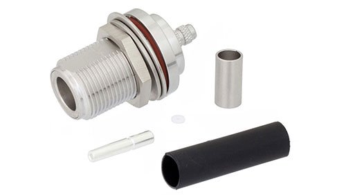
N-type Coaxial Connectors are one of the most common coaxial connector types used in wireless communication and sensing systems. This connector type has been around since the 1940s and was originally designed for military applications not exceeding 1 GHz maximum operating frequency. These coaxial connectors can be found in virtually all applications that operate below 6 GHz, though there are such connector variations that go as high as 11 GHz or even 18 GHz. N-type coaxial connectors are typically threaded connector types, though there are several variations, as there are with another common coaxial connector type, the SMA connector. N connectors were originally defined in MIL-STD-348 and come in both 50 Ohm and 75 Ohm versions. This is sometimes an issue as many manufactured versions of these connectors are not labeled as either 50 Ohm or 75 Ohm, and may be confused in broadcast, military, automotive, and other applications that may use both 50 Ohm and 75 Ohm N-type connectors, which are not typically compatible.
Like other coaxial connectors, there are female and a male N-type coaxial connectors, though there are hermaphroditic connector variations also available. These are less common than the typical threaded type, as hermaphroditic connectors tend to be expensive and are generally only used for test and measurement applications.
N-type coaxial connectors typically can handle more power than SMA coaxial connectors, as these connectors are larger and allow for wider spaces between the conductors. However, the extent of N-type connector power handling depends on the dielectric breakdown, connector design, connector material, and frequency of operation. Like other coaxial connectors, the power handling is a function of frequency and decreases at higher frequencies.
The 50 Ohm N-type connector is one of the most common connectors for test and measurement equipment and metrology applications for frequencies within range of precision variations of this connector (~11 GHz). Hence, there are many devices and components that operate to 6 GHz, and even X-band, that use these connectors as an interconnect interface. There are N-type connectors with attachments for bulkheads, coaxial cables, surface mount soldering (reflow), thru hole soldering, end launch, and even reusable end launch N-type connectors. There are also highly specialized versions of these connectors, such as high voltage (HV), reverse-polarity, left-hand thread, and others. Given the popularity of N-type connectors, there are a wide array of variations and customized adaptations well beyond the scope of this article.