

Highlights of Measuring Dielectrics With RF Equipment Part 3
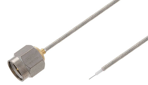
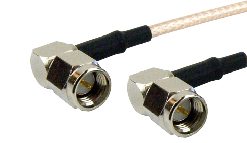
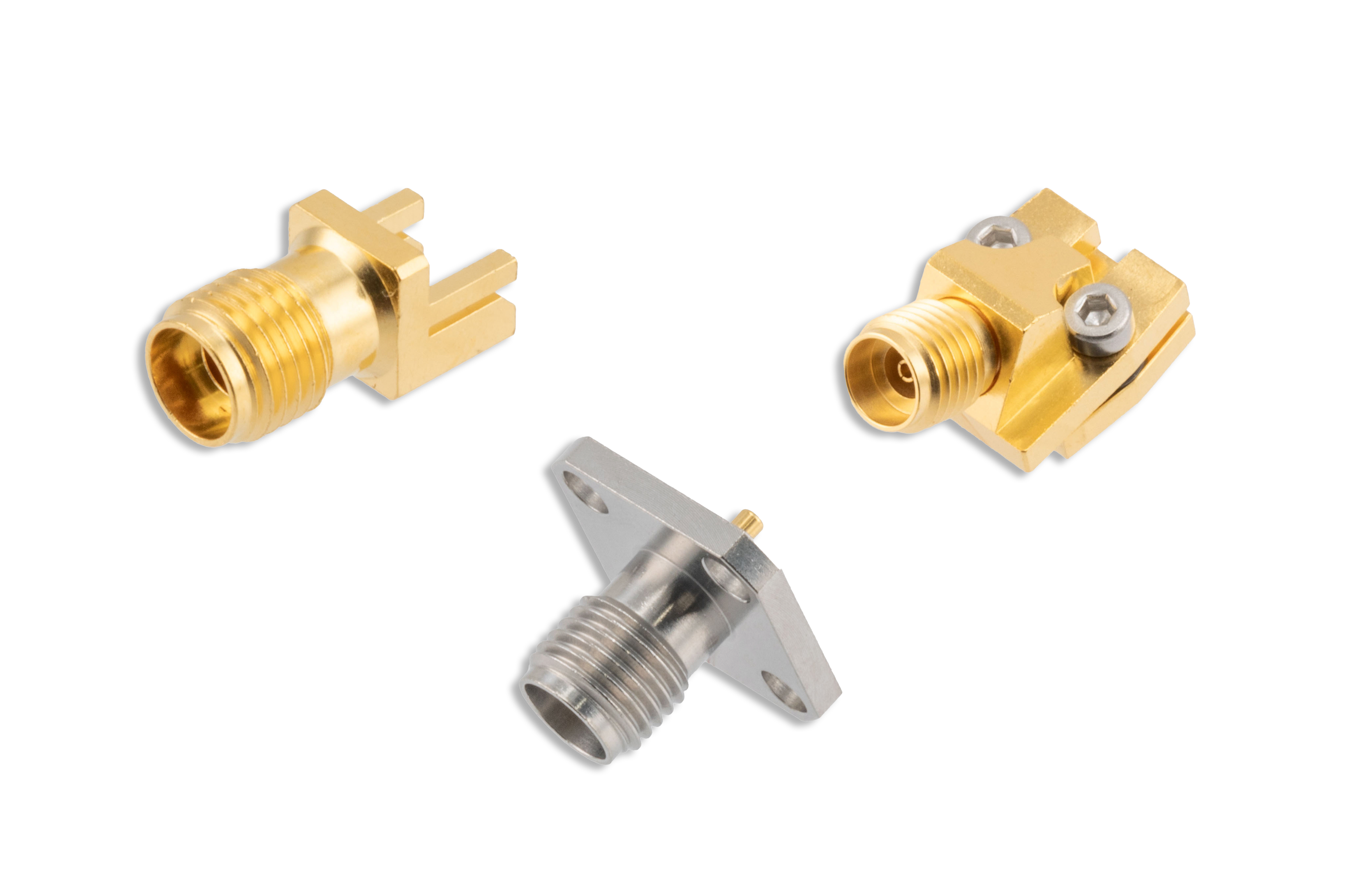
In the previous blogs in this series, the basics of dielectric measurement with RF equipment was discussed. This also included a highlight of two common methods of dielectric characterization using VNAs, transmission/reflection line method and Open-ended coaxial probe method. This section provides more insight into the free space method and resonant methods. Like other dielectric measurement methods, the methods described here make use of VNAs, Coaxial Cable Assemblies, High-speed End Launch Connectors, Coaxial GS/GSG Probes and Probe Positioner, various Waveguide hardware, and Waveguide Antennas.
Related articles
Peter McNeil | Sep 14, 2022 | Waveguide Terminations
A waveguide termination, or waveguide load, is a common waveguide component found in many RF systems, including radar, test & measurement, satellite communications, and aerospace communications. Similar to how RF coaxial terminations work, waveguide terminations absorb excess RF energy that enters the termination.
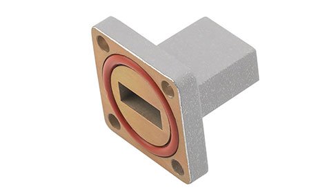
Waveguide Termination
Terminating a waveguide can be useful for a variety of reasons. For instance, with switching radar, if the transmitter needs to be switched off there will be some time before the high-power transmission devices can be deenergized. During this time period the transmission energy can be switched to a high-power waveguide load that safely absorbs the energy instead of the high-power RF signal energy being reflected back to the transmission devices or receiver devices. Another example is the termination of a directional coupler’s ports to realize certain configurations or enhance the coupler performance.
A waveguide termination is basically a waveguide flange, a waveguide, RF absorbing materials, and some form of thermal management/heat dissipation. The waveguide body is generally made of the same material as the termination heat sink and is commonly brass or aluminum but could be made of other engineering metals depending on the application. The RF absorbing material is often refractory ceramics, or some other stable RF absorbing material that can handle the high temperatures associated with absorbing RF engineering and effectively transfer the thermal energy to the thermal management features of the termination.
Depending on the power requirements, waveguide size, and other factors, there are several common options for waveguide thermal management. The most common for relatively low power terminations are just a straight body waveguide with the waveguide body being the RF absorber encapsulation and thermal management using passive cooling. Higher power waveguide loads can be designed with heat sink fins or even active cooling measures. Forced air cooling is the more common active cooling method used with waveguide terminations. However, liquid-cooled/water-cooled systems do exist for extremely high-power RF terminations. Another choice is to have a water coupled system, where water, or a water glycol mixture, is used as the RF absorbing material and thermal management transfer fluid.
The main electrical performance and features of a waveguide termination are frequency range (waveguide size), VSWR, and input power handling. Physical performance features, such as size, weight, and material are also significant concerns in many applications. Waveguide terminations are often plated or coated to prevent corrosion (passivation) and may also be additionally painted for enhanced environmental protection and thermal management considerations.